Synthesizable RS-232 UART Transceiver in VHDL
Introduction
This project implements a synthesizable, bidirectional RS-232 Universal Asynchronous Receiver-Transmitter (UART) module in VHDL. It was designed to interface an FPGA with an external PIC microcontroller and a MATLAB-based software GUI, requiring precise handling of asynchronous clock domains and hardware-level state machines.
Hardware & Constraints
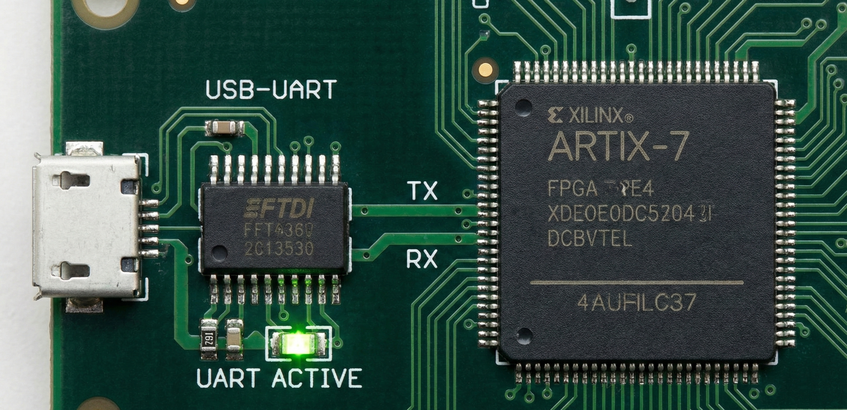
The target platform is the Digilent Cmod A7-35T FPGA board featuring a Xilinx Artix-7 chip. The system operates on a hardwired 12 MHz clock. To achieve the standard RS-232 baud rate of 115,200, the physical timing constraint requires exactly 104.167 clock cycles per bit (12,000,000 / 115,200). This mathematical constraint dictates the integer counter logic within the transmission and reception state machines.
System Architecture
The design is partitioned into modular, parameterized IP blocks:
-
Transmitter (
uart_tx): Utilizes a finite state machine (FSM) to assert a start bit, shift an 8-bit payload (LSB first) at 104-cycle intervals, and drive a stop bit. -
Receiver (
uart_rx): Implements a double-flop synchronization chain to mitigate metastability from asynchronous external signals. The RX FSM detects the falling edge of the start bit and deliberately delays sampling by 1.5 bit periods (156 clock cycles) to align with the center of the data “eye,” maximizing signal integrity before sampling the subsequent 8 data bits. -
Top-Level Integration (
lab06.vhd): Wraps the TX and RX components and maps the I/O to physical PMOD headers for external communication.
Verification Strategy
Pre-silicon verification was conducted using a self-checking VHDL testbench (uart_tb.vhd). The testbench instantiates the transmitter and receiver in a closed-loop configuration and automatically injects a worst-case alternating bit pattern (0xA5 / 10100101). VHDL assert statements continuously validate that the decoded receiver output matches the transmitted payload, ensuring timing alignment over data sequences without relying entirely on manual waveform inspection.
Hardware-in-the-Loop Testing
Following synthesis via Xilinx Vivado, the bitstream was validated on the physical Cmod A7 hardware. The RX and TX pins mapped to the PMOD connector (srx and stx) were physically bridged for loopback testing. Bidirectional communication was successfully verified in real-time using a custom MATLAB serial interface (gui06.m).
Conclusion
Building this transceiver from scratch reinforced the ability to translate high-level communication protocols into constrained, cycle-accurate digital logic.
The full VHDL source code, self-checking testbenches, and Xilinx Vivado constraints for this project can be found on my GitHub repository.